Hardware
| Hardware Contents: | |
| 1. | The Mosaic CCD |
| 2. | The Dewar |
| 3. | The Arcon Controllers |
| 4. | The CCD Shutter |
| 5. | The Filter Track |
| 6. | Filters for Mosaic |
| 7. | Operation of the Guider TVs |
| 8. | Correctors |
| 9. | Atmospheric Dispersion Corrector |
The Mosaic CCDs
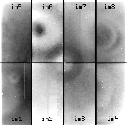
The Mosaic Imager features eight 2048 (serial or pixels/row) x 4096 (parallel or pixels/column) 15 m pixel CCDs arranged as an 8192 x 8192 pixel detector. The CCDs are read out through a single amplifier per chip simultaneously to 8 controller inputs (on 4 Arcon controllers). The resulting mosaic array is a square about 5 inches on an edge. The gaps between CCDs are kept to about 0.7 mm in the row direction and 0.5 mm in the column direction. [see Figure 3.1.1 showing an image labeled with chip numbers.] We have populated the Mosaic Imager with thinned, AR coated SITe CCDs. These chips have only minor flaws which have little effect on their scientific performance, but they do require careful calibration to attain excellent flat-fielded images. Please see current CCDs for some characteristics of the Mosaic II chips.
Figure 3.1.1: A Flat-field (R band) map of the CCDs in Mosaic I with their "extensions" (im1, im2, im3, ...) as used in the IRAF nomenclature (see section 5).
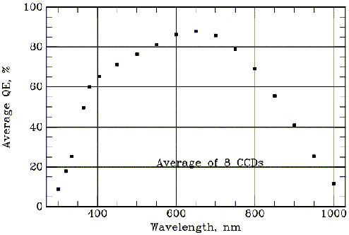
Figure 3.1.2 shows the average QE for the 8 CCDs at KPNO. Individual CCDs may deviate from this curve as shown in Figure 3.1.3.
Figure 3.1.3: The QE differences relative to the average for the 8 SITe CCDs in Mosaic I. Also shown are the readnoise (RN) and gain (GN) values for each CCD.
The Dewar
The Mosaic dewar is a large (6.3 liter) vacuum vessel radiatively coupled to the CCD mount. It is the large round cylindrical object in the center of Figure 3.2.1. The hold time of the dewar is 18 hours. It will be filled by an observing technician at the start and end of each night.
Several temperatures within the dewar are monitored and displayed in the Mosaic Graphical User Interface (GUI). The CCDs should be between -95and -105C. The dewar tank is cooled to -166 C or cooler. A good way to detect the exhaustion of LN2 is the warming of the "fill neck" temperature, which is normally near 0 C. If this temperature begins to rise much above zero or any of the temperature boxes turn red, call for assistance to have the dewar filled.
The dewar containing the 8 CCDs is the silvery, cylindrical object in the middle. It is surrounded by the filter track which is housed in the large black oval that extends horizontally across most of the picture.
The Arcon Controllers
The eight CCDs are read out through four Arcon controllers. These controllers run at 100 kpix/sec per CCD, yielding a readout time of ~2.5 minutes (in the single amplifier mode) and complete the transfer to disk on the data reduction computer. Data values are stored as 16-bit unsigned integers. For further details about the Arcon controller systems, see the technical paper by Roger Smith.
The data taking computer (ctioa0) is a 125 Mhz Sun Sparcstation 10 running SunOS. It has sufficient resources to manage the data acquisition, but not much more. The large data volume is handed off to the reduction computer (ctio4m) via fast Ethernet for all analysis and reductions, thereby relieving the data taking machine of unnecessary loads. The reduction computer is a fast Sun Ultra with >45 Gbytes of disk and >512 Mbytes of RAM.
Figure 3.3.1: A view of the Mosaic system indicating 2 of the 4 Arcon controllers. Also the south guide TV housing can be seen, as well as the large Mosaic dewar.
The CCD Shutter
The shutter consists of a pair of opposing sliding blades, one of which has rectangular slots open for the guide field. The blades are attached to pneumatically driven cylinders to provide very fast control of the shutter. This design allows the TV guide fields to be shuttered independently of the science field. In the guide mode, the closed shutter still allows the TV guide cameras to see the sky. In the dark mode, these fields are closed as well. The acquisition software controls which mode the shutter remains in between exposures. For object observations, the shutter goes to the guide mode before the exposure begins. For requested observation types of dark, flat, or zero, the shutter goes to the dark mode before the exposure begins (and remains in this mode after the exposure and readout are completed). Note that the TV fields are always open when the shutter is open; the different shutter modes only control the TV fields when the science shutter is closed. If you have been taking darks, flats, or zeros, you may need to set the shutter mode to guide in order to get light to the TV guide camera.
The time for the blades to move completely across the field is 23 msec. The motion of the blades during both opening and closing are in the same direction so that the exposure level is nearly constant over the array. The motion of the shutter blades is along columns. All exposure times are shorter than the nominal time requested, in the mean, by 22 milliseconds (measured May 31 2000), ie if you request a 2 second exposure the time is really 1.978 seconds. The nom-uniformity of exposure is approximately +/- 5 milliseconds. Thus you can do short exposures (eg 1 second), particularly if you take account of the 22 millisecond offset. A one second flat field exposure will have a +/- 0.5% percent non-uniformity du to shutter shading. A caveat is that we do not have data to test whether there is any temperature effect (these measurements weer done at 11C) or changes with time, or inclination of the instrument (we were pointed at the white spot). So to be VERY safe, avoid exposures shorter than approx 5 seconds.
The Filter Track
The filter track holds 14 filters. For each filter position, there is a filter for the CCD field, and two separate filters for the two TV fields. Separate filters are used so that a narrow bandpass science filter does not constrain the observer to find very bright guide stars. Normally, one would use clear (BK7) filters for the TV, but one can use a red filter to minimize moonlight or match the science filter more accurately. One might want to match the science filter, at least approximately, to minimize a guider drift. Even at the 4-m, residuals after the correction from the ADCare of order 0.1-0.2 arcsec. This, and all filter decisions, must be made ahead of time, as the filters can only be changed during the day by a qualified observing technician.
Adapters exist to allow the use of 4-inch-square filters in the Mosaic filter track. At the 4-m, the 4-inch filters illuminate approximately 5.5K X 5.5K pixels (46% of the total sky area).
The positioning of the filter track is highly repeatable. However, the acceleration of the track can occasionally dislodge dust particles between filter moves, particularly if intervening movements have turned the filter upside down. In all cases, the filter track software moves the track in the direction that minimizes the distance moved to reach the requested filter position.
In addition to the 14-position filter track, there is a manual slide that can hold a single filter of the same size (5.75 inches square). This may be used, for example, to hold a bandpass filter when polarization filters are used in the track. Use of this ìhand-insert filterî changes the focus. At the 4-m, changing, inserting, or removing this filter can only be done at the maintenance (Northwest Annex) position.
Filters for Mosaic
Physical Dimensions: To fully utilize the field of view of the 8Kx8K, filters must be 5.75 inches (146 mm) square, and have 5.43 inches (138 mm) clear aperture. The optimum thickness that preserves image quality over the entire field of view is 0.47 inches (12.0 mm). All NOAO mosaic filters adhere to these specifications to maintain an approximately parfocal condition. We have determined focus offsets for some of the filters, and will enter more when we measure them. You also may want to tweak the TV camera focus (watch the FWHM graph on the PC Guider GUI) if your focus change is more than (say) 50 microns.
Currently available filters and Offsets: MOSAIC FILTER LIST
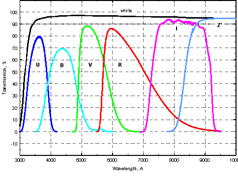
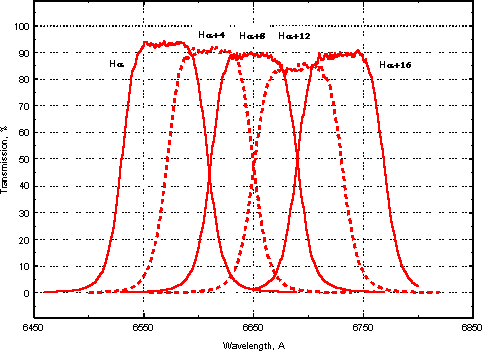
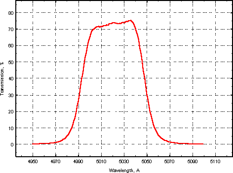
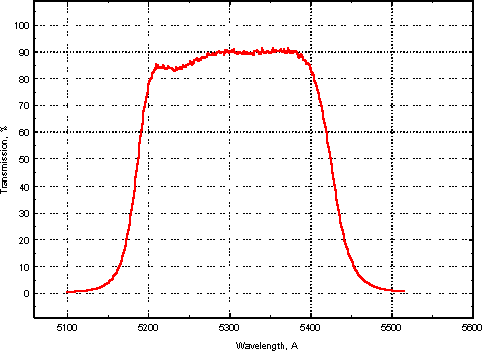
Transmission curves: See Figures 3.61, 3.62, and 3.63 for plots of the current KPNO broad-band, H, and [OIII] filter transmission curves. ASCII Tables that numerically describe the transmissions are available on the Mosaic Web Pages.
Figure 3.6.1: The broad band filter set, including the "White" and Gunn Z' filters. The U-band filter is based on the same formulation as our 4" filter set (liquid CuSO4 + UG-1).
Figure 3.6.2: The current set of H-alpha (plus redshifted) filters. Note that H-alpha+16 serves as a [SII] filter.
Figure 3.6.3: The current [OIII] filter available for Mosaic. It will be replaced soon with one that is slightly blue-shifted, for improved performance at the 0.9-m
Figure 3.6.3: The current [OIII] filter available for Mosaic. It will be replaced soon with one that is slightly blue-shifted, for improved performance at the 0.9-m
Figure 3.6.4: The [OIII] off-band filter available for Mosaic.
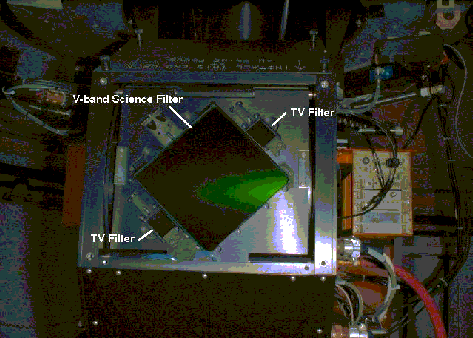
Figure 3.6.4: The V-band filter installed in the filter track. The 2 TV guider filters are visible to the lower left and upper right of the science filter. An Arcon controller can be seen in the background to the right.
Operation of the Guider TVs
Guiding with the Mosaic is accomplished using one of two TV cameras on the north and south sides of the science field. These are intensified fiber-optically coupled CCD cameras ("ICCDs"), and so, they can be damaged if exposed to bright light. The video signal from the selected TV camera is fed to the leaky guider system. The field of view of each camera is about 2.2 arcmin on a side at the 4-m.
The TVs field of view is fixed with respect to the science field. At the 4-m, the fields are approximately 1440 arcsec north and south of the center of the science field. TV focus can be moved remotely; offsets are -1.9 and -3.2 at the 4-m, for the north and south TVs, respectively.
At a given location, suitable guide stars are almost always available without moving the telescope from the desired position. We find that we can guide at the 4-m on stars as faint as V=20 in full moon.
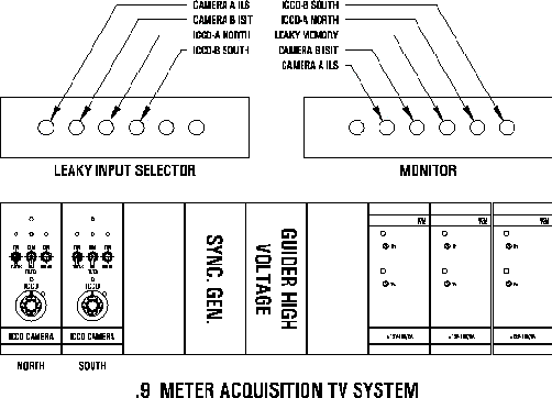
The TVs and leaky guider are controlled by the telescope operator at the 4-m. The operator selects the N or S TV on the distribution panel (see Figure 3.7.1), and also selects viewing the "leaky" memory output. For the selected TV, on the ICCD Control Panel:
- Turn the high-voltage potentiometer completely counterclockwise (10 turn pot)
- Toggle the power switch on (on TV screen, pixel defects will appear)
- Neutral density switch should be down (off)
- Push the momentary button to enable high voltage
- Slowly turn the high voltage potentiometer clockwise, monitoring TVs until guide stars appear
When switching between the two TVs, be sure to turn the high voltage potentiometer counterclockwise and turn off high voltage on the TV no longer in use.
Figure 3.7.1: A schematic drawing of the layout of the TV control panels. Only the two leftmost panels in the lower rack are used with the Mosaic TVs. The upper rack is used to select which TV/video signal is seen on the monitor and whether or not it goes through the "leaky" guider.
The ICCD guide cameras at CTIO are controlled by the PD GUIDER (documentation here soon, see the write-up in the Console Room beside the monitor). The system has a nice GUI, with graphs that show you how well the guider is performing (offsets, total counts, fwhm), and a picture of the star field, with guide box. Your Telescope Operator is familiar with the PC Guider and will operate it for you.
Correctors
A description of the CTIO 4m PF ADC can be found in the preprint by Tom Ingerson located here (a postscript file). A drawing of the optical layout is also available.
The PFADC is based on a 6 element design by Bingham, similar to a corrector used on the WHT. The two rotating ADC prisms are shaped and serve as the corresponding elements of a basic 4-element corrector. Each doublet is made of glasses (LLF1 and PSK3) which have almost the same indicies of refraction but different dispersions. The cemented surfaces of the doublets are slightly inclined, so both act like zero-deviation prisms with a small dispersive power. When the axes of the prisms are 180 degrees out of phase, their dispersions cancel and the system has essentially the same image quality as a basic 4-element design (e.g, Wynne 1987). The optical design provides excellent un-vignetted images at all wavelengths withing the design range from 3500A to 10000A over a 48 arcmin field. Optical design specification call for image quality of 0.25" fwhm in the center and 0.5" fwhm at the edge for all wavelengths in the design range.
At CTIO, the ADC is enabled from the TCS computer at the operators consol. The TCS display should show a red blinking ENABLED keyword under ADC, and the position angles of the two elements are also posted. This is the continuous tracking mode for the ADC and should be the default.
Image quality: The 4-m images are excellent across the entire 36'x36' Mosaic field; images as good as 0.6 arcsec FWHM have been seen with this corrector. PSF variations are typically within ~15%.
Image Scale: The 4-m scale is slightly variable (6.3%) due to pincushion distortions, from 0.261" per pixel at the center (f/3.1) to 0.245" per pixel (f/3.3) at the corner of the field.
Atmospheric Dispersion Corrector
The Earth's atmosphere disperses the light from stars significantly when observing away from zenith. The effect is greatest and similar at U and B where the stellar image is stretched, for example, ~0.5" at a zenith distance of 45° (1.4 airmasses), and 0.9" at 60° (2 airmasses). The ADC prisms can be configured via a rotation to counter this effect nearly completely, thereby greatly reducing the elongation of the image introduced by the atmosphere.
While the ADC is not necessary to compensate for atmospheric dispersion when using narrow-band filters, the guide cameras have separate broad-band filters [see sec 2.7] that will see the effects of atmospheric dispersion. Differential refraction between the guider and the science CCDs will change as a function telescope position, and will cause blurring for long exposures at high zenith distances if the ADC is set to DISABLED. Note that, unlike the Mayall 4-m PF corrector, the Blanco corrector is achromatic essentially over its full wavelength range thus if the ADC ie ENABLED then at any zenith distance image shifts will not occur if TV filters are changed. Also, we expect the astrometric properties of the field to change very little with wavelength, although we have as yet to quantify this.
This section was last updated on March 14 2000.
Updated on January 28, 2025, 10:25 am
