C/KOSMOS User Manual
Mask Design Software for C/KOSMOS
S. Points, P. Martini, J. Elias, & C. Briceño
Contents
Introduction
Installation
Making C/KOSMOS Masks
How to Submit Masks
Change Control
References
Acknowledgements
Introduction
C/KMS (C/KOSMOS Mask Simulator) is a mask design software package for the C/KOSMOS instruments on the CTIO Blanco 4-m and KPNO Mayall 4-m telescopes, respectively. C/KMS is a modified version of the LMS (LUCI Mask Simulator) software suitable for C/KOSMOS. Potential users of C/KMS are strongly encouraged to become familiar with the LUCI LMS User's Manual before beginning to work with C/KMS. This C/KMS manual assumes familiarity with LMS. From here, we refer to the COSMOS/KOSMOS mask design software as "KMS".
The KMS software can design masks for both COSMOS on the CTIO 4-m Blanco telescope and for KOSMOS on the KPNO Mayall 4-m telescope.
Installation
The current version of KMS is available here:
KMS is written in Tcl/Tk and has been tested on both GNU/Linux and MacOS operating systems. The version available here includes a GNU/Linux binary for version 2.7.3 of ESO's SkyCat Tool.
Users of MacOS and other operating systems will need to download the SkyCat binary appropriate to their operating system. ESO no longer actively supports the SkyCat tool, so if you are having problems with the installation, please consult with your local computer support staff. The KMS software will work with any version of SkyCat that will run on your computer, so don't worry if the only version that works is an older one.
The main web page for SkyCat at ESO is here:
The KMS tar file above will unpack into a subdirectory containing all of the code. The path to this code should then be set to the environment variable KMSROOT, e.g.
setenv KMSROOT $HOME/kms_v162
One can then run the software with the command:
bash $KMSROOT/bin/kms.sh
Making C/KOSMOS Masks
The software is configured for the KOSMOS plate scale. If you are designing masks for COSMOS, you will need to edit the appropriate parameter file, which is named "KOSMOS.isf" and which you can find in the $KMSROOT/lib/mos directory. Around line 20 in the file you will find an entry for FOCSCALE.VALUE. There should be a value for the Mayall and another value for the Blanco that is commented out with "#". Comment out the Mayall value and uncomment the Blanco value. For reference, the values are:
Mayall: 6.6245
Blanco: 6.5929
The Blanco value is with the ADC, which is the recommended configuration for MOS mode.
Starting the KMS software
From the command line:
bash $KMSROOT/bin/kms.sh &
You should now have a screen that look like this:
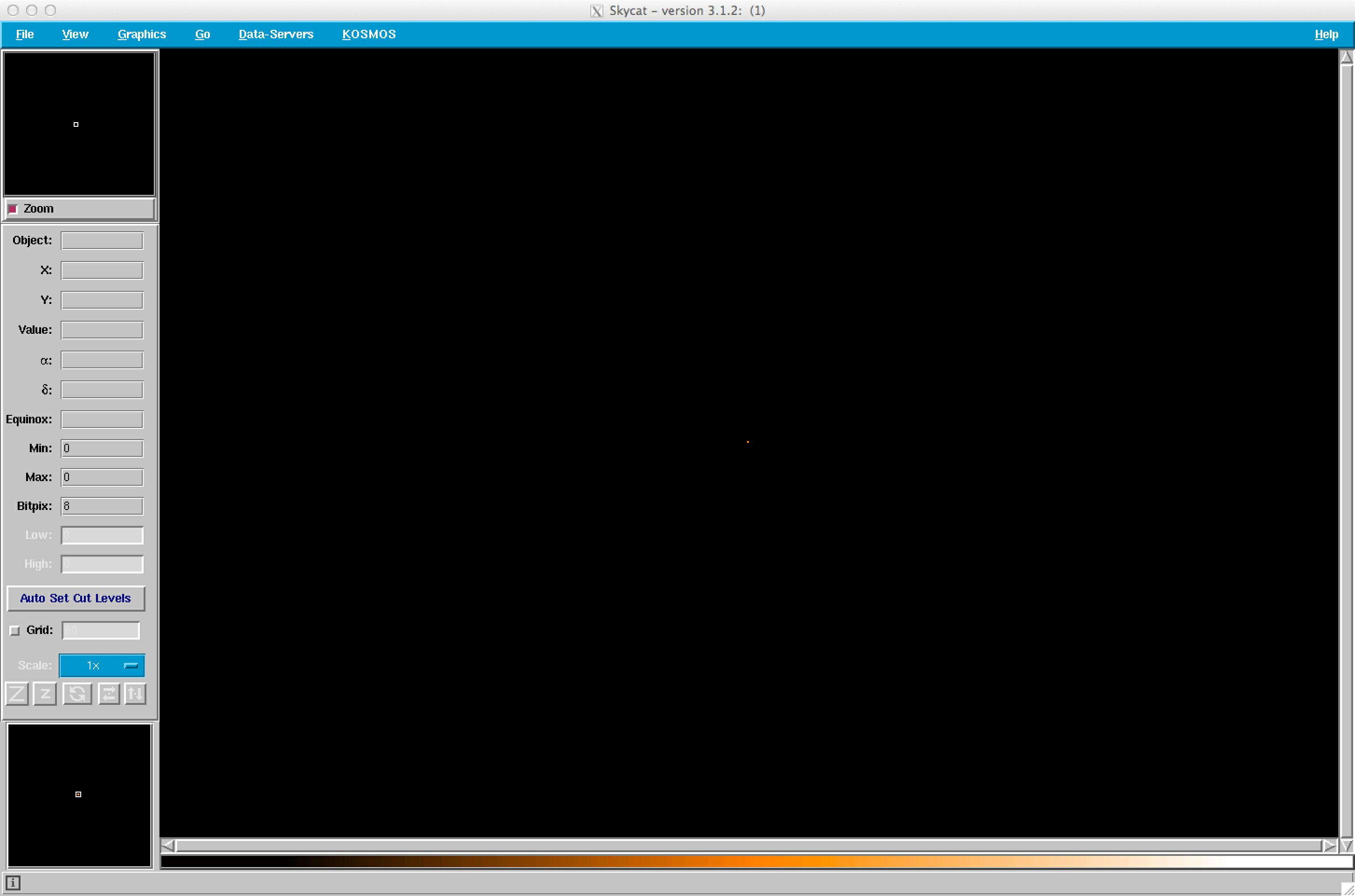
KMS has a KOSMOS pull-down menu with similar options to the LUCIFER pull-down menu for LMS. Click on the File/Open option:
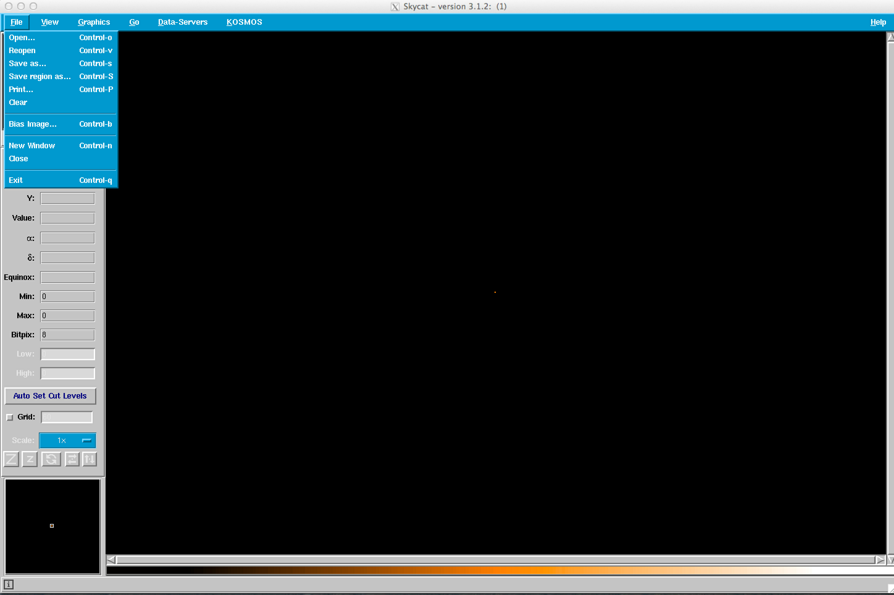
and select an image. You can use any image with a decent WCS solution, such as DSS or SDSS images, or your own data if appropriately calibrated. The default area is 10 arcmin x 10 arcmin; you may want specify a somewhat larger area (something in the range from 12 arcmin x 12 arcmin or 15 arcmin x 15 arcmin).
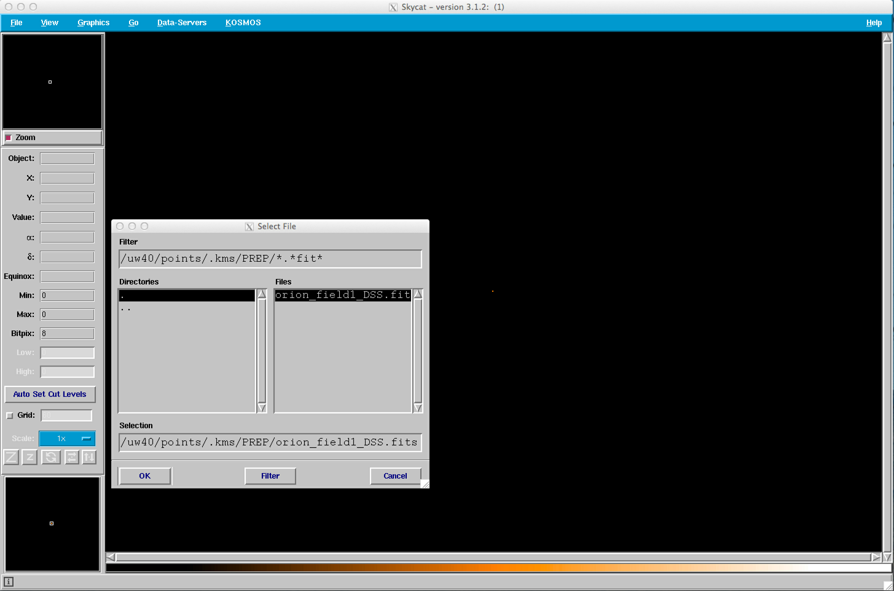
In this example, we have selected an image toward Orion, orion_field1_DSS.fits.
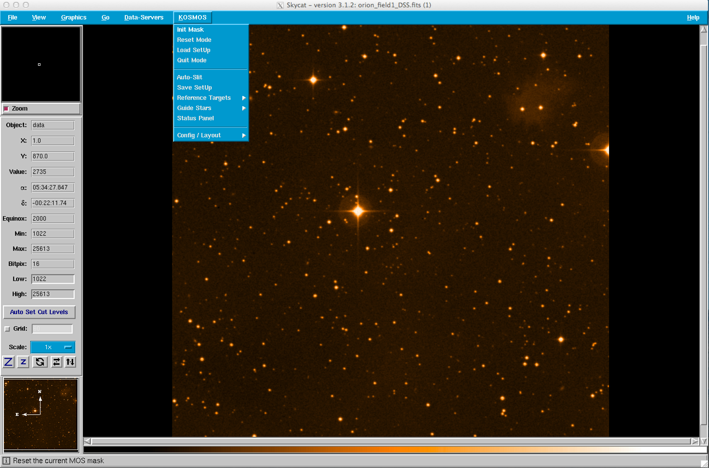
The KMS design GUI should now look like:

Once the FITS file with WCS information has been loaded, select the Init Mask option under the KOSMOS tab to draw an outline of the C/KOSMOS field, which is shown and described below.
 |
 |
Field of View
The figure above shows a screen shot of KMS immediately after Init Mask has been selected (click on the image for a larger version). The outlines are similar to those for LMS. The large, blue rectangle is the 2k by 4k detector footprint. The white square marks the 10' by 10' field for imaging and multi-object spectroscopy.
Designing a Mask
Slits are assigned to objects in a similar manner to LMS. The Config/Layout submenu under the KOSMOS menu has a range of length and width options. The default is a 1.0" by 10" slit. When designing your mask, you should set the default slit width to 0.9" (or some othered desired value). The figures below show the process of configuring the slits.
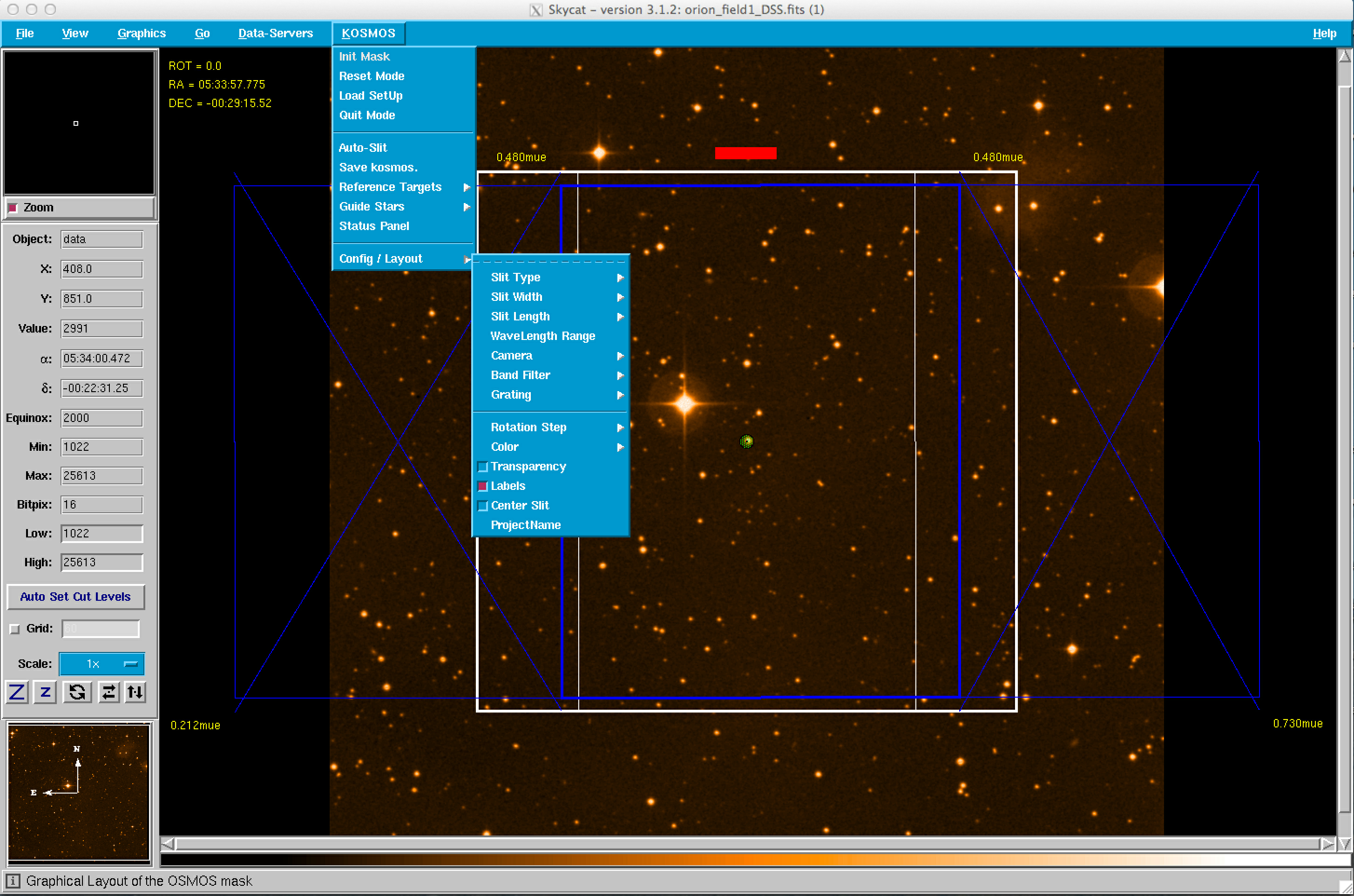 |
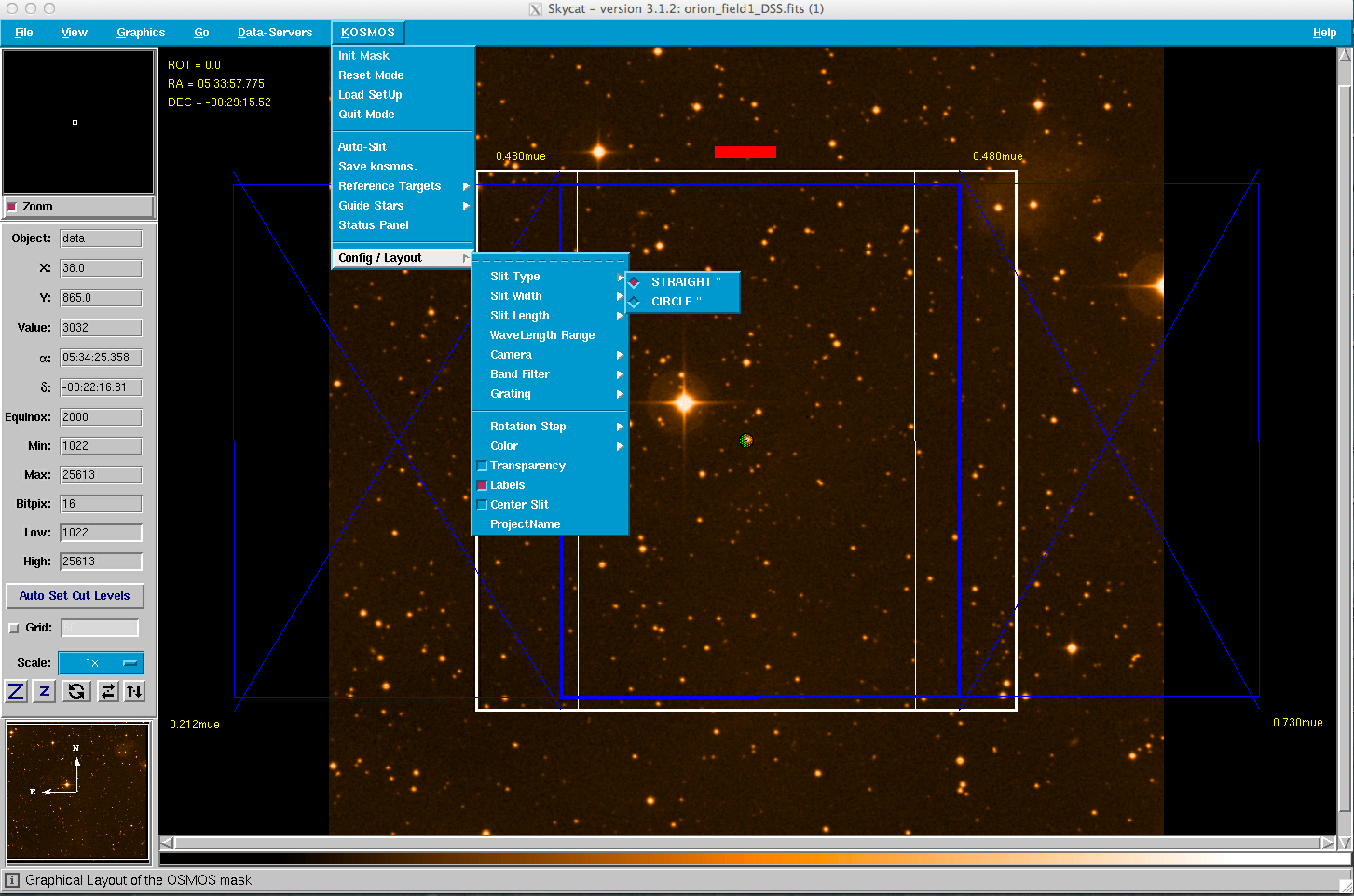 |
 |
 |
Setting Mask Rotation
WARNING: It is posible to design masks for unusable position angles! Please ensure that you consider the constraints below, as the SkyCat tool will not provide and warning or error messages.
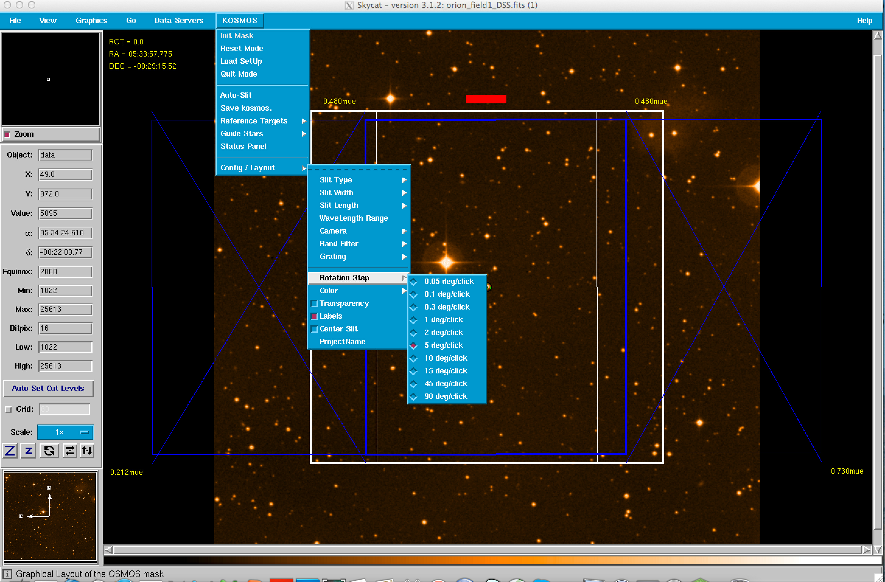
You should set the position angle for the mask first, because any change in the position angle will erase any slit that you have created. Please be aware that the allowable position angles for KOSMOS and COSMOS are different, and remember that unlike a long slit 0 degrees and 180 degrees are not interchangeable. The usable PA range for KOSMOS is 0-180 degrees. The usable PA range for COSMOS is everything except 88-92 degrees. The PA in the KMS window is rotated by positioning the cursor at the center of the mask and center-clicking. The default increment is 5 degrees. To change the default rotation increment, click on the KOSMOS Config/Layout menu item and select the appropriate rotation increment, as shown below.
Placing Slits and Alignment Boxes
Once the slit properties, i.e., shape, width, and length have been defined in the Config/Layout menu, the placement of slits and alignment boxes is relatively straightforward. As mentioned above, one should have changed the default slit width from 1" to 0.9" (or some other value). Alignment boxes are simply implemented as 4" by 4" slits. One can either place the slits by hand or one can load a file with the slit centers. First, we will discuss the placement of the slits by hand.
Placing Slits by Hand:
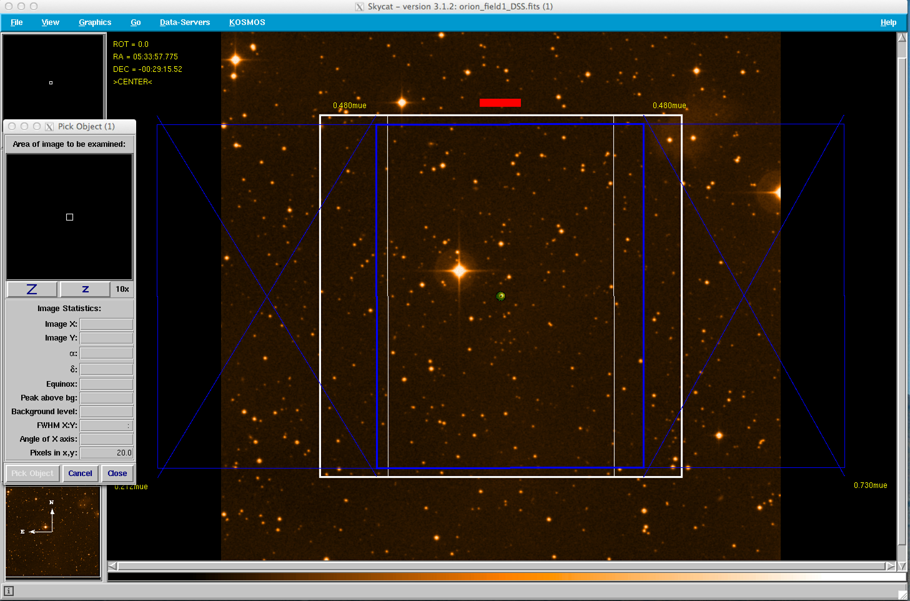
After the slit properties have been selected, one should click on the Config/Layout submenu and select the Center Slit option to activate the Pick Object zoom option as shown in the figures below. The Pick Object window allows one to accurately center on an object by hand. Selecting slits by hand is most convenient when one has few objects for the slit mask. It is important to note that once slits are placed on the mask, they cannot be deleted. Therefore, if there are any misplaced slits, one will need to start again by resetting the mask.
 |
 |
Placing Slits by Using a Coordinate List:
As mentioned above, the current version of KMS does not allow one to delete slits after they have been placed. Therefore, some may find it more convenient to place the slits using a coordinate list. At a minimum, the coordinate list has the following format:
| ID | RA | DEC |
| -- | -- | -- |
| Obj1 | 05:33:57.736 | -00:27:51.45 |
| Obj2 | 05:33:56.932 | -00:28:44.83 |
| … | … | … |
| ObjN | 05:33:57.283 | -00:32:25.31 |
This file is available for download here. Please note that this file is a tab separated list.
To place slits using a coordinate file, open the Data-Servers and select the Local Catalogs option. This will allow you to open your local object list as shown in the figure below.
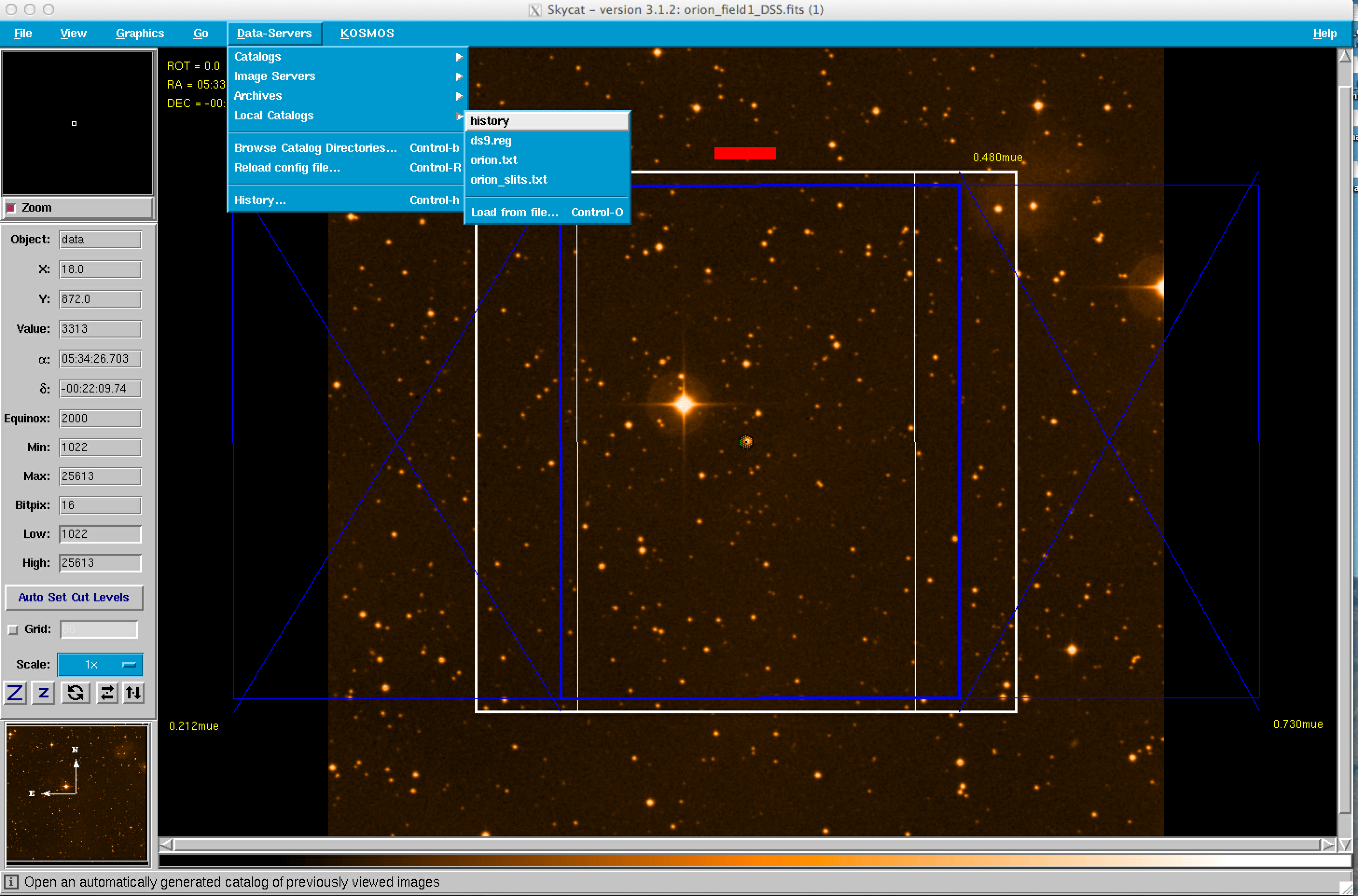
After the catalog is selected, return to the KOSMOS menu and select the Auto-Slit option as shown below.
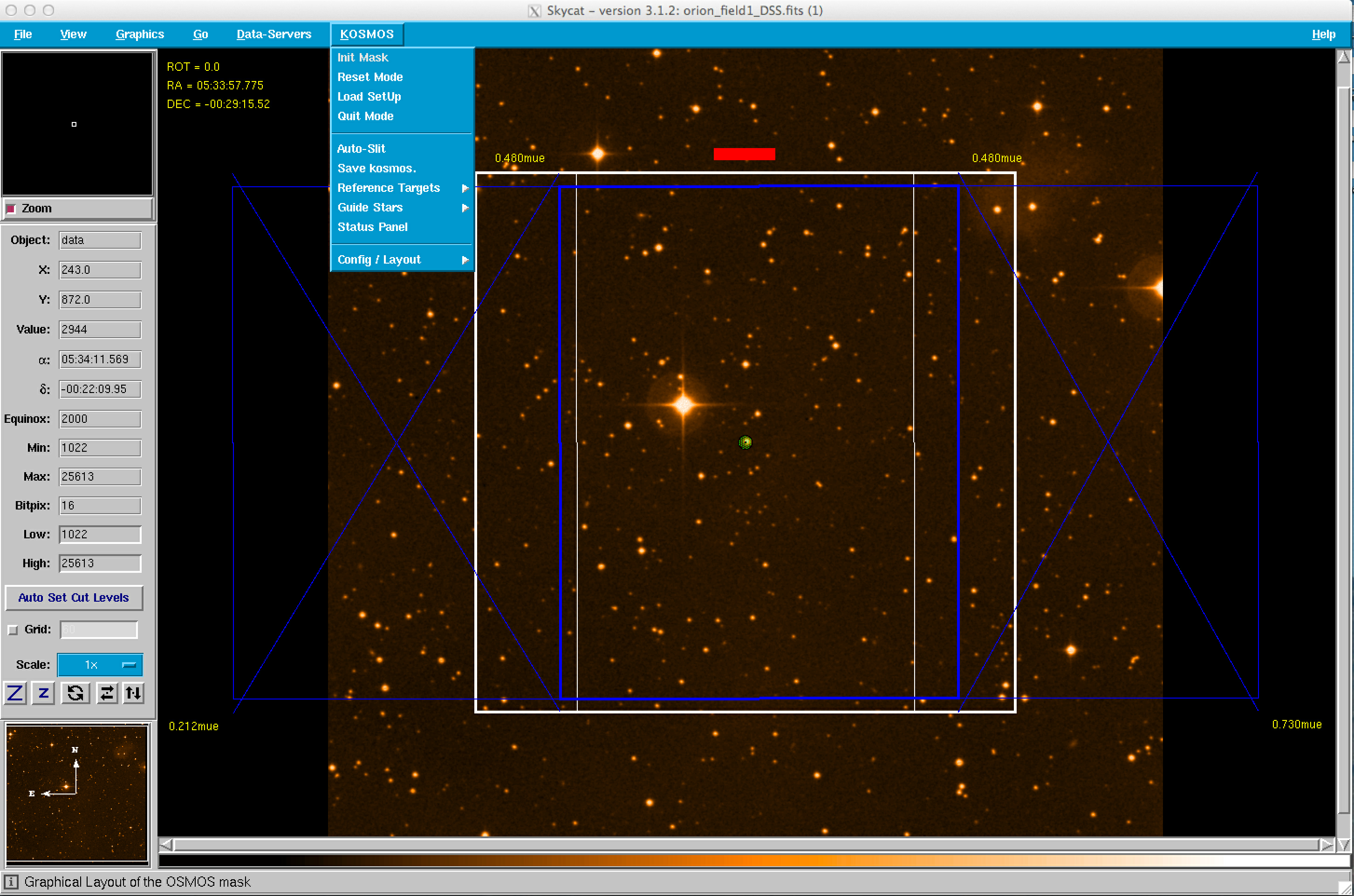
The objects listed in the catalog file will now appear in the KMS GUI.
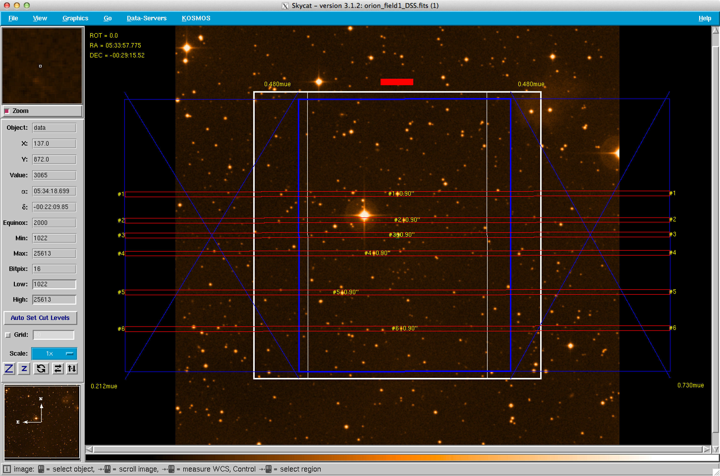
If one is going to use catalog files to place slits, it is recommended that one has a separate calatog for objects and another for alignment stars. The reason for this is that the Auto-Slit option will give all objects in the catalog the same slit parameters, i.e., slit width and slit length. Catalog files should be located in the $HOME/.kms/PREP directory.
Before selecting alignment stars, set the slit width and slit length to these values in the Config/Layout submenu. The figure below shows an example with 3 alignment boxes (Objects #1, #2, and #3) and five 0.9" by 10" slits. Note that the width of the three alignment boxes is specified as 4.00" and the slits are 0.9" wide. One can also see that the slits are longer (10") than the alignment boxes (4").
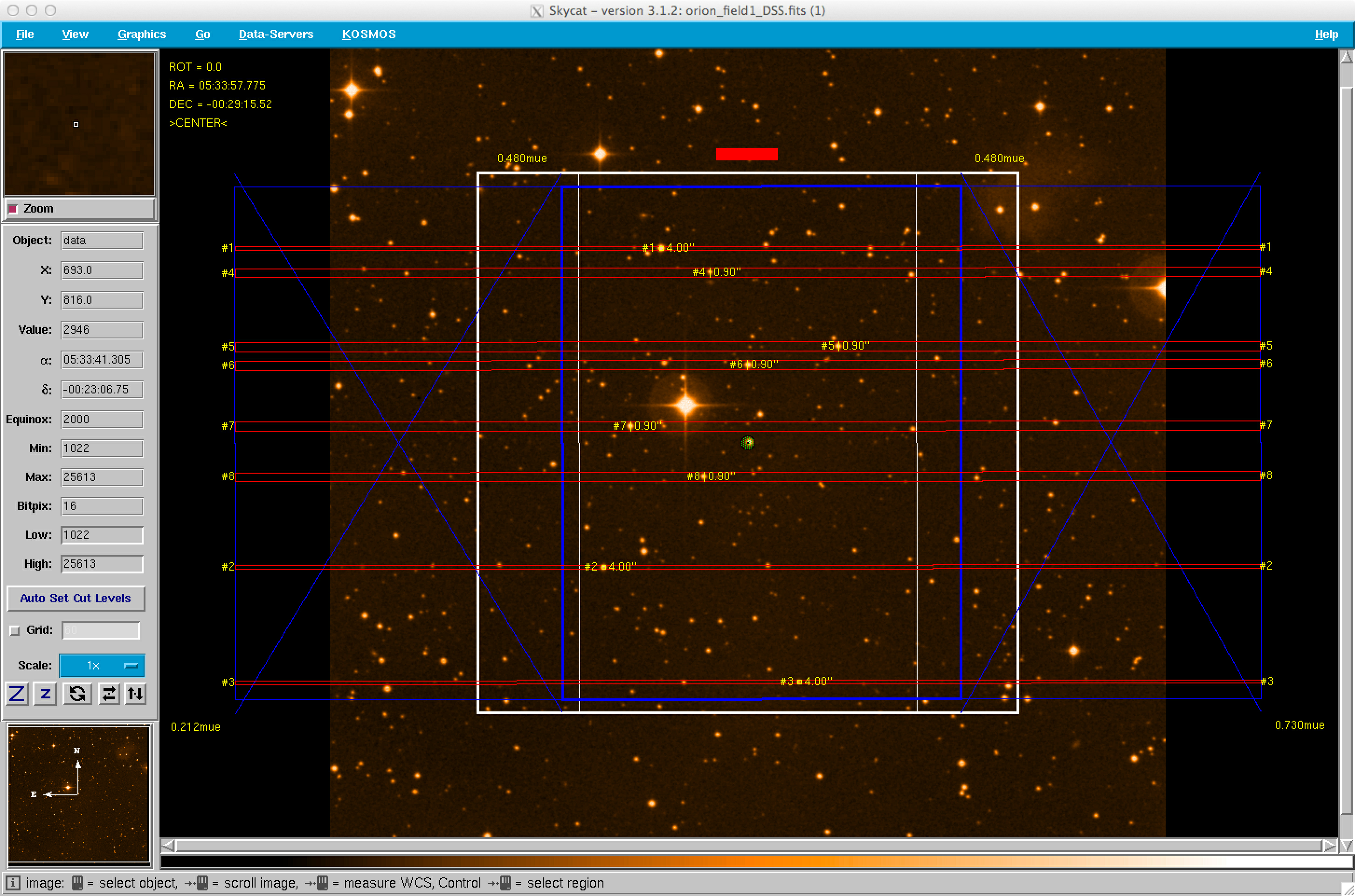
We recommend a minimum of 3-5 alignment stars with r = 12-16 mag and that these stars be relatively uniformly distributed within the imaging area. In principle only two stars are necessary to align a mask, but in practive issues such as poor astrometric solutions, saturated stars, proper motions that have not been corrected, poor placement of the stars (e.g. all in the same quadrant), uncertain stellarity, and bad pixels/columns may impact one or more stars. Five stars, all separated from each other by a few arcminutes, is even better if you are not an expert or do not have complete confidence in your astrometric catalog. Extra stars allow the observers freedom to eliminate one or more problematic stars, if necessary. Note that the alignment stars should be selected from catalogs (or images) with the same astrometric solution as the targets. The alignment stars should be in the magnitude range r = 12-16 mag to avoid saturation in a short acquisition image, yet bright enough to yield a precise centroid measurement. A final suggestion: If you have extra space on your mask, and your targets are quite faint (fainter than about 20 mag), consider placing a few extra slits on brighter objects. These may provide valuable, additional checks on the quality of the mask alignment at the telescope.
Output Files
KMS produces two output files. The rootname of these files has the format: mods.N.name where N is some integer and name is the Project Name (if specified). These output files are:
kosmos.N.name.kms: ascii text file
kosmos.N.name.gbr: Gerber file
These files are written by default to the $HOME/.kms/SET/ directory. The KMS file contains detailed information about the mask design, including the mask center, position angle, Mask ID, and information about each slit, alignment box, and guide star. This file is also useful to have at the telescope, as it is used for mask alignment. The Gerber file contains a description of the mask for the laser cutting machine. It is essentially identical to the postscript file, although it also contains the Mask ID. One viewer for Gerber files is gerbv.
How to Submit Masks
Send the Gerber (.grb) and kms (.kms) files to your scientific staff contact or the instrument scientist. They will then ship all of these files to kosmos@noao.edu. You must submit your masks no later than one month before the start of your observing run.
Change Control
Current version: v1.62-20131217
Initial, development version. While this version has been used to successfully construct masks, it does not permit some options. Specifically, once a slit or alignment box is placed, it is impossible to delete or move. Therefore, an incorrectly placed slit or alignment box requires that the designer start over.
References
MMS Webpage at Ohio State
MODS Webpage at LBTO
LMS User's Manual
LUCI Webpage at LBTO
The ESO SkyCat Tool
gerbv A Gerber (RS-274X) viewer
Acknowledgements
We are very grateful to the MODS team for supplying the MMS code. The MMS code is based on the LMS code which was based on the ESO FIMS code.
Last Updated: 2014 October 27 [sdp]
Updated on April 28, 2025, 10:28 am