SOI Overview
Figure 1: Two views of the SOI mounted at one of the bent Cassegrain foci of the SOAR telescope. The smaller blue cylinder is the CCD mosaic dewar and is flanked by the two rectangular Leach controllers, the round black part is the cable wrap, and the large blue tube bolted onto the telescope is the main body of the instrument holding the linear ADC prisms, one of which can move over a distance of nearly one meter. The drawing shows the basic lay-out of the instrument in a cut-out view. From left to right the light encounters: ADC prisms, optics module, two filter slides, the shutter, and finally the CCD mosaic.
The SOI step-by-step Observer's Guide (NEW!)
Optics:
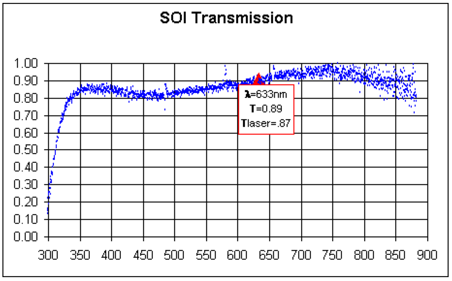
The SOI optics consist of a 6 element focal reducer and field corrector, that converts the f/16.63 beam of the SOAR Telescope to f/9.82, preceded by a linear, "trombone style", Atmospheric Dispersion Corrector (ADC). These optics were designed to deliver images of < 0.18 arcsec FWHM (equivalent to 80% encircled energy within D80 < 0.27 arcsec) at the zenith and <0.34 arcsec FWHM (D80 < 0.51 arcsec) at 70deg zenith distance, in each of the U, B, V, R, I broad band filters, and over the entire field. The glasses selected, and the use of SOLGEL over MgF2 coatings on all external surfaces ensure high transmission over the entire 310nm-1050nm passband. The measured transmission curve is shown below in Figure 2. Note that the transmission below 400nm is an underestimate of the true transmission due to limitations of the measuring device, and should be considered a lower limit.
Filters:
Filters are mounted in two filter cartrides each with space for 4 filters, plus one blank position, so that up to 8 filters can be installed in the instrument at any time. Although the cartridges were designed to be easily removable, the process of changing them out still requires at least 30 minutes, and we currently have no spare cartridges. Thus it is strongly recommened that users design their programs to avoid filter changes during the night. Filters may be up to 100mm square and up to 10mm thick. Smaller filters may be accommodated with special adapters but must be at least 64mm square to avoid vignetting. To see the list of the currently available filters, together with transmission curves, click HERE. Filters from the CTIO filter list are also available.
CCDs:
The SOI focal plane is imaged onto a mini-mosaic of two CCD's with the following properties:
CCD mounting gap:
The two CCDs in the SOI are mounted with their long sides parallel and spaced 102 pixels apart, resulting in a 7.8" gap between the individual CCD images. This image of 30 Doradus shows how a single SOI image looks. The gap can be filled by taking dithered images. We recommend taking at least 3 images with 10" steps to produce a complete combined image with no gap.
Flat Fields and Fringing:
The CCDs show fringing in the I, i' and z' bands (see example here) at the 10%, 3% and 12% level, respectively. In the U band some hatched structure is seen but this flat fields out perfectly. Here are examples of flatfields at the Bessell U, B, V, R, and I bands (click the band to see the link).
Ghosts, stray light etc..:
The use of interference filters - which select their passband by reflecting the rest of the light - results in haloes around bright sources. These haloes look like images of the entrance pupil of the telescope with the secondary mirror spider clearly visible, especially when the seeing is good. We have some stray light from encoders in the SOI rotator on the CCDs in the I band. The level is about 0.2 ADU per second, or less than 1% of the dark sky background. We are working on eliminating this stray light. A complete report on these and other optical effects in the SOI is given in a report, available here.
Read-out:
The chips are read out by two amplifiers each. Various read-out and binning modes will be available. Note that a seeing disk of 0.45" is still well-sampled by 2x2 binned pixels, so that only for the very best seeing and using the tip-tilt mode should the CCDs be used in unbinned mode. At present, the tip-tilt mode is not yet offered. SOI is no longer offerred in slow read-out mode (as of 2008 Nov).
Focusing:
Focusing of the SOI is done by charge shifting on the CCD, and moving the telescope focus between steps by automatic software. The number of steps, step size, and exposure time per subexposure can be chosen by the observer.
Guider:
The instrument incorporates a fast readout CCD guide camera which can be used to drive the telescope's tertiary mirror in order to partially compensate atmospheric Tip and Tilt, and correct telescope tracking jitter. The actual performance of this system has yet to be determined, but it is expected that Tip-Tilt correction will be possible with guide stars as faint as R=14, with useful guiding performance down to R=19. The field of view of the guide camera is only 7" square, however, the probe can be placed anywhere within a 12 arcmin diameter patrol field. Normally the probe should be kept outside the central 6x6 arcmin to avoid blocking part of the science field. However, when the best possible Tip-Tilt correction is required it may be desireable to select a guide star close to the science target accepting the obstruction of parts of the field.
Updated on January 29, 2025, 7:22 am


